Assembly of Valves
Valve assembly is the assembly process of the various components of valve according to specific technical conditions. Valves are usually assembled in the order and method specified by the process using the valve body as the reference part.
During the assembly process, the parts must be handled gently to avoid bumps and scratches on the machined surface.
After final assembly, it is necessary to check whether the movement of the valve opening and closing parts is flexible and there is no disturbance and whether the valve meets the requirements of the drawings.
After all appropriate inspections, the valve can be tested.
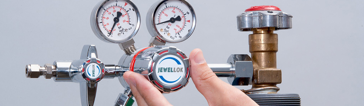
A valve assembly can be defined as a system that centres around the valve’s mechanism, and also includes auxiliary devices such as the casing, actuation mechanisms of both electrical and non-electrical kinds, and even sensors. This system is important for regulating the flow of fluid or gas in a machine. The individual valves in this system are typically made of metal or plastic and are generally operated via a solenoid. The assembly also includes one or more check valves, which allows the fluid or gas to flow in one direction but not the other. While valve assemblies can be obtained as a complete set for configurations of larger sizes, individual parts can be purchased separately and assembled to reduce the cost of operation.
The whole machine is the most basic unit of valve assembly, and several parts make up the parts of the valve (such as valve cover, valve clack parts, etc.). The assembly process of several parts forming parts is called component assembly, and the assembly process of several parts and components forming a valve is called general assembly. Assembly work has a great impact on product quality. Even if the design is accurate and the parts are qualified, if the assembly is improper, the valve will not meet the specified requirements, and even seal leakage will occur. Therefore, special care should be taken to adopt a fair assembly method to ensure the quality of the final product of the valve. The assembly process defined in the form of documents in production is called the assembly process specification.
Preparation before assembly
Before assembling the valve parts, it is necessary to remove the burrs formed by machining and welding residues, clean and cut fillers and gaskets.
CLEANING OF VALVE PARTS
As a valve installed by the fluid pipeline, the inner cavity must be clean. In particular, valves used in nuclear power, medicine, and food industries have stricter requirements on the cleanliness of the valve cavity in order to ensure the purity of the medium and avoid medium infection. Before assembling, the valve parts should be cleaned, and the chips, residual oil, coolant and burrs, welding slag and other dirt on the parts should be washed and cleaned. The valve is usually cleaned by spraying with alkaline water or hot water (kerosene can also be used for scrubbing) or cleaning in an ultrasonic cleaning machine. After the parts are ground and polished, the final cleaning is required. The final cleaning is usually to clean the sealing surface with gasoline, then dry it with compressed air and wipe it with a cloth.
PACKING AND GASKET PREPARATION
Graphite filler is widely used because of its advantages such as corrosion resistance, good sealing performance and low friction coefficient. Packing and gaskets are used to prevent the medium from leaking through the valve stem and bonnet and the joint surface of the flange. These accessories must be prepared for cutting and receiving before the valve assembly.
Inspection before valve installation
① Check carefully whether the valve model and specifications meet the requirements of the drawings.
② Check whether the valve stem and valve clapper open flexibly, and whether they are stuck or skewed.
③ Check whether the valve is damaged, and whether the thread of the threaded valve is correct and intact.
④ Check whether the combination of valve seat and valve body is firm, the connection of valve disc and valve seat, valve cover and valve body, valve stem and valve disc.
⑤ Check whether the valve gasket, packing and fasteners (bolts) are suitable for the requirements of the nature of the working medium.
⑥ The pressure reducing valve that is outdated or left for a long time should be disassembled, and dust, sand and other debris should be cleaned with water.
⑦ Clear the port seal and check the degree of sealing. The valve disc must be closed tightly.
Valve pressure test
Low pressure, medium pressure and high pressure valves should be subjected to strength test and tightness test. Alloy steel valves should also be subjected to spectrum analysis on the shell one by one, and the material should be reviewed.
STRENGTH TEST OF VALVE
The strength test of the valve is to test when the valve is open to check the leakage on the outer surface of the valve. For valves with PN≤32MPa, the test pressure is 1.5 times the nominal pressure, the test time is not less than 5min, and there is no leakage at the shell and packing gland.
VALVE TIGHTNESS TEST
The test carried out with the valve in the fully closed state is to check whether there is leakage on the sealing surface of the valve. The test pressure, except for butterfly valves, check valves, bottom valves, and throttle valves, should generally be carried out at the nominal pressure. At working pressure, it can also be tested with 1.25 times the working pressure, and the sealing surface of the valve disc is qualified.
General regulations for valve installation
1. The valve installation position should not hinder the operation, disassembly and overhaul of the equipment, pipeline and valve body itself, and the aesthetic appearance of the assembly should be considered.
2. For valves on horizontal pipelines, the valve stem should be installed upwards, or installed at a certain angle, and the handwheel should not be installed downwards. The valve, valve stem and hand wheel on the high-altitude pipeline can be installed horizontally, and the opening and closing of the valve can be remotely controlled by a vertical low chain.
3. The arrangement is symmetrical, neat and beautiful; the valve on the standpipe, if the process permits, the valve handwheel is most suitable for operation with chest height, generally 1.0-1.2m from the ground, and the valve stem must follow the operator Direction installation.
4. Valves on side-by-side risers should have the same centerline elevation, and the clear distance between handwheels should not be less than 100mm; the valves on side-by-side horizontal pipes should be installed staggered to reduce the distance between the pipes.
5. When installing heavier valves on water pumps, heat exchangers and other equipment, valve brackets should be installed; when the valves are frequently operated and installed more than 1.8m away from the operating surface, a fixed operating platform should be installed.
6. If there is an arrow mark on the valve body, the direction of the arrow is the flow direction of the medium. When installing the valve, make sure that the arrow points in the same direction as the medium flow in the pipeline.
7. When installing flanged valves, ensure that the end faces of the two flanges are parallel and concentric with each other. Double gaskets are not allowed.
8. When installing a threaded valve, in order to facilitate disassembly, a threaded valve should be equipped with a union. The setting of the union should consider the convenience of maintenance, usually the water flows through the valve first and then the union.
Precautions for valve installation
1. The valve body material is mostly made of cast iron, which is brittle, so it must not be hit by heavy objects.
2. When moving the valve, throwing is not allowed; when lifting or hoisting the valve, the rope should be tied to the valve body, and it is strictly forbidden to tie it to the handwheel, valve stem and flange bolt holes.
3. The valve should be installed in the most convenient place for operation, maintenance and overhaul, and it is strictly prohibited to be buried in the ground. The valves on the pipelines directly buried and in the trenches shall be equipped with inspection wells to facilitate the opening and closing and adjustment of the valves.
4. Ensure that the threads are intact and undamaged. Wrap hemp, lead oil, or PTFE tape on the threads. When screwing, use a wrench to clamp the hexagonal valve body screwed into one end of the pipe.
5. When installing the flange valve, pay attention to tighten the connecting bolts diagonally, and use even force when screwing to prevent the gasket from running off or causing the valve body to deform and damage.
6. The valve should be kept closed during installation. For threaded valves close to the wall, it is often necessary to remove the valve stem, disc and handwheel during installation before they can be turned. When disassembling, you should turn the handwheel to keep the valve open before disassembling.
Commonly used assembly methods for valves
There are three commonly used assembly methods for valves, namely, complete replacement method, repair method and selection method.
COMPLETE SWAP METHOD
When the valve is assembled using the complete interchange method, each part of the valve can be assembled without any trimming and selection, and the assembled product can meet the specified technical requirements. At this time, the valve parts must be processed completely in accordance with the design requirements to satisfy the requirements of dimensional accuracy and geometric tolerances. The advantages of the complete interchange method are: assembly work is simple and economical, workers do not need a high degree of skill, the production efficiency of the assembly process is high, and it is easy to organize assembly lines and organize specialized production. However, in absolute terms, when adopting a complete replacement assembly, the machining accuracy of the parts is higher. It is suitable for valves with absolutely simple structures such as globe valves, check valves, ball valves, and valves with medium and small diameters.
SELECTION METHOD
The valve is assembled by matching method, and the whole machine can be processed according to economic precision. When assembling, a certain size with adjustment and compensation function is selected to achieve the specified assembly accuracy. The principle of the matching method is the same as that of the repair method, except that the method of changing the size of the compensation ring is different. The former is to change the size of the compensation ring by selecting accessories, and the latter is to change the size of the compensation ring by trimming the accessories. For example: the top core and adjustment gasket of the control valve type double-disc wedge gate valve, the adjustment gasket between the two bodies of the split ball valve, etc., is to choose special parts as compensation parts in the dimensional chain related to assembly accuracy. Adjust the thickness of the gasket to achieve the required assembly accuracy. In order to ensure that the fixed compensation parts can be selected in different situations, it is necessary to pre-manufacture a set of gaskets and shaft sleeve compensation parts hydraulic control valve models of different thickness sizes for selection during assembly.
REPAIR METHOD
The valve is assembled by the repairing method, the parts can be processed according to economic precision, and then a certain size with adjustment and compensation function is repaired during assembly to achieve the specified assembly goal. For example, the gate plate and valve body of the wedge gate valve, because the processing cost required to realize the interchange is too high, most manufacturers use the repair method. That is, in the final grinding of the gate sealing surface to control the opening size, the plate should be matched with the opening size of the valve body sealing surface to achieve the ultimate sealing requirement. Although this method adds the plate matching process, it greatly simplifies the dimensional accuracy requirements of the previous processing process. The special personnel of the plate matching process are skillful, and generally speaking, it will not affect the production efficiency. Valve assembly process: The valves are individually assembled on a fixed site. The valve parts and components assembly and general assembly are carried out in the assembly workshop, and all the required parts and components are transported to the assembly site. Usually component assembly and general assembly are distinguished by how many groups of workers are carried out at the same time, which not only shortens the assembly cycle, but also facilitates the application of special assembly tools, and the requirements for the skill level of workers are relatively low.
Some foreign manufacturers or high-tech valves also adopt the mode of assembling the suspension line or assembling the rotary table.
Valve assembly
The valve is usually assembled with the valve body as the reference part in the order and method specified by the process. The parts and components should be reviewed before assembling to avoid the parts that are not deburred and cleaned from entering the final assembly. During the assembly process, the parts should be handled with care to avoid bumping and scratching the processing personnel. The moving parts of the valve (such as valve stems, bearings, etc.) should be coated with industrial grease. The bonnet and the flange in the valve body are mostly connected by bolts. When tightening the bolts, respond to the scale, interweave, tighten repeatedly and evenly, otherwise the joint surface of the valve body and the bonnet will produce flow control valve due to uneven surrounding forces. leakage. The handle used for tightening should not be too long to prevent the pre-tightening force from being too large and affecting the bolt strength. For valves with strict requirements for pre-tightening force, torque should be used to move the hand, and the bolts should be tightened according to the specified torque requirements. After the final assembly is completed, the holding mechanism should be rotated to check whether the movement of the valve opening and closing parts is maneuverable and whether there is any jamming. Whether the installation direction of the valve cover, bracket and other parts of the pressure reducing valve meets the requirements of the drawing, the valve can be tested only after all the reviews have passed.